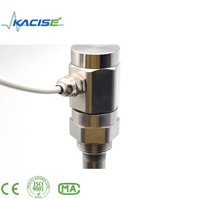
Capacitive level transmitter_Measures oil level in tank trucks and oil depots_Without display
Capacitive level transmitter
Capacitive intelligent liquid level sensor is a liquid level (material level) transmitter that can be used for liquid, oil, solid, interface and measurement. There are no moving parts, the reliability is greatly improved, it is not affected by water vapor, dust or condensation, and has the advantages of stable and reliable long-term operation, high sensitivity, good linearity, high temperature resistance, high pressure resistance, etc. The intelligent liquid level meter is a two-wire (loop powered) 4~20mA DC measurement signal, easy to adjust, wireless transmission, 485 transmission, etc. Can be widely used in petroleum, chemical, metallurgy, electric power, paper, pharmaceutical and other fields.
Capacitive level transmitter Specification:
●Detection range: 0.1~30m
●Capacitance measurement range: 10PF~500PF
●Accuracy: 0.1 class, 0.2 class, 0.5 class, 1 class
●Pressure range: -0.1MPa~32MPa
●Probe temperature resistance: -50~250℃
●Ambient temperature: -40~85℃
●Storage temperature: -55℃~ 125℃
●Output signal: 4~20mA, 485 communication, etc.
●The communication distance of wireless output level sensor is less than 200 meters, and the power supply voltage is 3.3-36V (optional battery power supply)
●Power supply voltage: 5~36V DC
●Level sensor material: 316 stainless steel, 1Gr18Ni19Ti or PTFE
●Long-term stability: ≤0.1%FS/year,
●Temperature drift: ≤0.01%FS/ ℃ (within the range of 0~70 ℃)
●Explosion-proof grade: ExibIICT6
●Protection level: IP67
Capacitive level transmitter Structure
Capacitive liquid level sensors have different structures due to different application occasions and parameters, but in general, its main structure can be roughly divided into two parts, namely the sensor part and the transmitter part. as the picture shows:
A in the picture shows the sensor, which directly probes into the container equipment or measures
in the measured medium of the meter tube
B and C in the figure are the gas phase and liquid phase connection flanges of the liquid level measurement and control instrument, which are used for the connection of the equipment flanges, and the liquid and pressure in the equipment are drawn to the measuring cylinder.
D in the figure shows the measuring cylinder of the liquid level measurement and control instrument, which can form a capacitance with the sensor electrode.
E shown in the figure is the sewage flange, which can regularly discharge the dirt in the liquid level measurement and control instrument to the outside, keep the inside of the measuring tube of the liquid level measurement and control instrument clean, and prevent the sensor from adhering to the dirt.
F shown in the figure is the Capacitive level transmitter, which is a conversion device from capacitance to standard current signal, and is the central part of the entire liquid level measurement and control instrument. Its main function is to receive the capacitance change increment caused by the liquid level change sent by the sensor, and then After conversion, it outputs 4-20mADC standard current signal. This transmitter adopts military integrated devices, with low power consumption, high temperature resistance, strong reliability, and meets the requirements of intrinsic safety.
Note: There is a sealing part between the transmitter and the measuring tube, which is composed of several seals, which can ensure that the measured medium is in contact with the sensor but will not leak out, causing harm. This section is an important sealing part, please do not disassemble it without the consent of the manufacturer to avoid accidents.
Display
Capacitive level transmitter Calibration
Although the analog adjustment has been made before the product leaves the factory, in order to allow the user to further experience the performance of our product before use, it is recommended that the user perform a simple verification. You can remove the whole set of instruments for calibration. (But do not disassemble the parts of our products)
The calibration of the external liquid level measurement and control instrument is shown in the figure :
The Capacitive level transmitter verification steps are as follows:
1) Prepare a transparent water pipe, mark it with a scale or fix it with a ruler, so that the actual liquid level can be observed and calibrated during calibration. In addition, prepare an ammeter (DC) with a precision of more than three digits, several rubber stoppers, and enough test medium (which can be replaced by water).
2) Connect one end of the transparent water pipe to the liquid phase port of the liquid level measurement and control instrument, block the sewage outlet, and keep the gas phase port unobstructed, and then turn on the power after confirming that the wiring is correct.
3) Add the medium from the upper end of the transparent tube, the medium flows through the liquid phase tube into the liquid level measurement and control instrument, and the liquid level is added to several points with different heights, because at this time the liquid level in the transparent tube is measured with the liquid level measurement and control instrument. The liquid level in the meter cylinder is exactly in line. At this time, read the value of the ammeter, and then compare the height ratio corresponding to the output standard 4-20mA signal with the collected current value to check the accuracy of the level meter (Note: In order to It is easy to calculate. Generally, several points are taken at 0%, 25%, 50%, 75% and 100% respectively, and the corresponding currents are 4mA, 8mA, 12mA, 16mA and 20mA respectively. The capacitive level transmitter range should correspond to the center of liquid phase and gas phase respectively).


